The last post in this series showed what can happen to the optics path of an XRD system in the wrong environment after several years of neglect. The end result of this kind of build-up is attenuation of the beam. The user will see this as a loss of intensity, but little else. In the XRF world, things are a little different because everything in the beam path can be expected to fluoresce as well as attenuate the beam. Depending upon the position and type of material, this can cause a range of interesting effects.
In the most basic case, the beam is simply attenuated as it would be in the XRD causing a loss of intensity. This would be the case with certain types of blockages in the incident beam. Several years ago I got a call from a senior tech at Bruker who was trying to help a client remotely. They’d been running fine until their intensities abruptly dropped nearly in half across the board. Checking the electronics and searching for evidence of a broken sample yielded no answers. Running previously analyzed samples proved that this was definitely not sample related. Owing to the urgency of their situation, I flew out right away with a solid kit of spare parts only to find a Post-It note sitting right on the port of the tube. Just in case there was any doubt, it had the identifier of the first sample which exhibited the symptoms written on it. It must have gotten stuck to the bottom of the cup before being loaded into the autosampler and carried all the way into the measurement position. We had a good laugh (and still do).
Other attenuation issues aren’t so obvious. A client running heavy greases in a He environment saw a 90% drop in light element intensity while heavy elements performed fine. After some remote trouble-shooting we were able to eliminate several possibilities, but fell short of a real solution. As it turns out, the issue was caused by a crack in one of the He flush lines. These instruments don’t simply flood the chamber with He during this cycle. Rather, they start by opening two He valves (one high flow and one low flow) while turning on the vacuum pumps. Once the lines are purged, the valves close and a vacuum is pulled on the chamber. At this point, the pumps shut off and the chamber is vented to He. The split hose was leaking a very small quantity of air into the chamber at the same time it was venting to He. Even this very small amount of air was enough to devastate light element intensities.
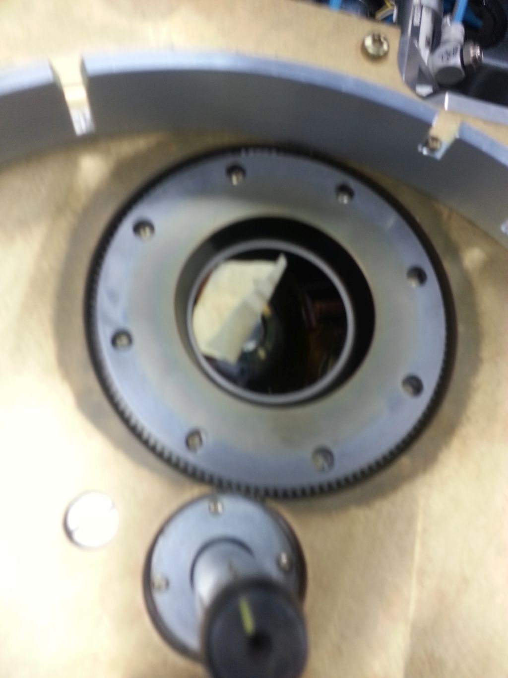
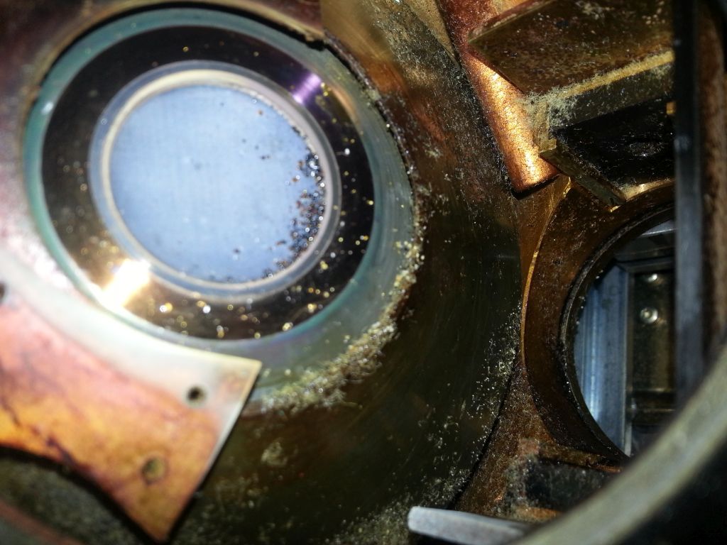 The pictured issue is another very common problem. Dust from powdered samples or worse, spills or drips from liquid samples can build up on the port of the tube. The result of contamination like this is usually minimal attenuation, but it can result in a very noticeable change in the reported intensities for a given element. Most users would catch this when running a monitor standard and many would simply run a drift correction to compensate, but the best course of action is to get your service provider involved right away. They’ll be able to assess the situation quickly and might offer a better solution than simply patching the issue with a data massaging correction. At least they’ll be in the loop if the symptoms become more serious.
There are some options for keeping your port safe from this kind of contamination. We like superfluous films which keep bits of material from falling onto the tube. Mylar, Kapton (Polyimide) and Prolene (Polyprolylene) are popular choices depending upon your application. Bruker systems starting with the S4 offer a filter position with a Be shield which protects the tube window itself and works well. More exotic options (inverted optics) promise to eliminate this problem, but this offers its own challenges. For instance, the users most concerned about this kind of contamination are running liquids. Pulling a vacuum on a liquid cup makes a mess no matter where your optics are and running a liquid in an inverted cup is an added complication and opportunity for error that we’d prefer to avoid.
Sorry, the comment form is closed at this time.