AN ANALYTICAL XRAY SERVICES LABORATORY
Feel free to call us: 940-784-3002

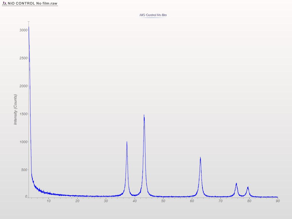
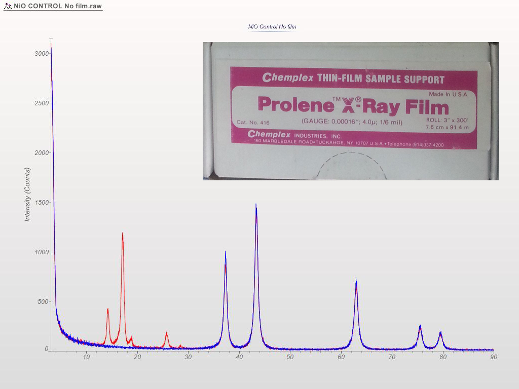
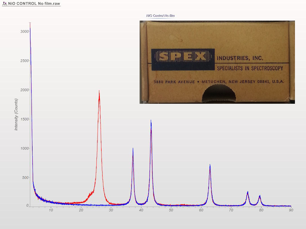
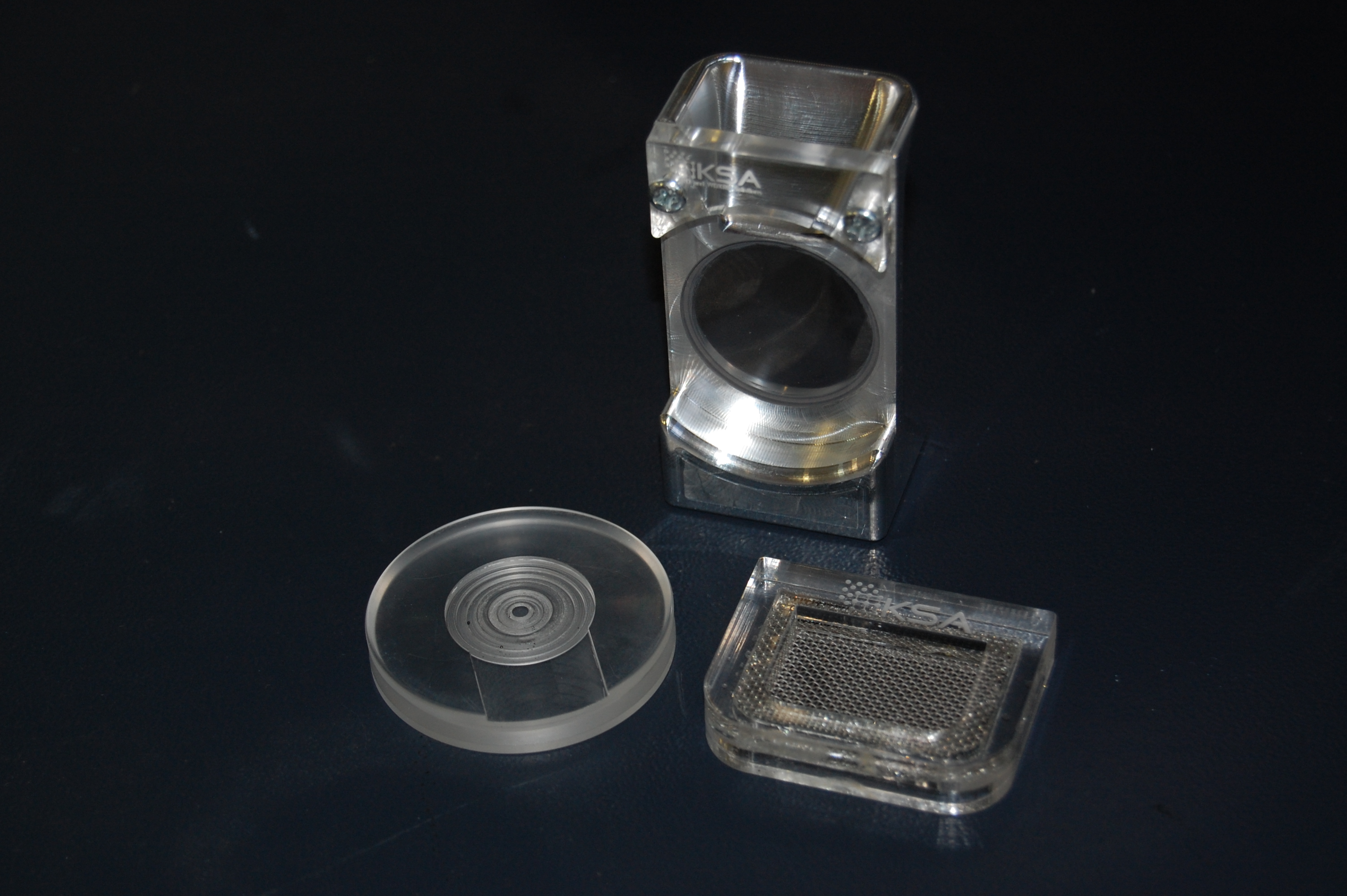
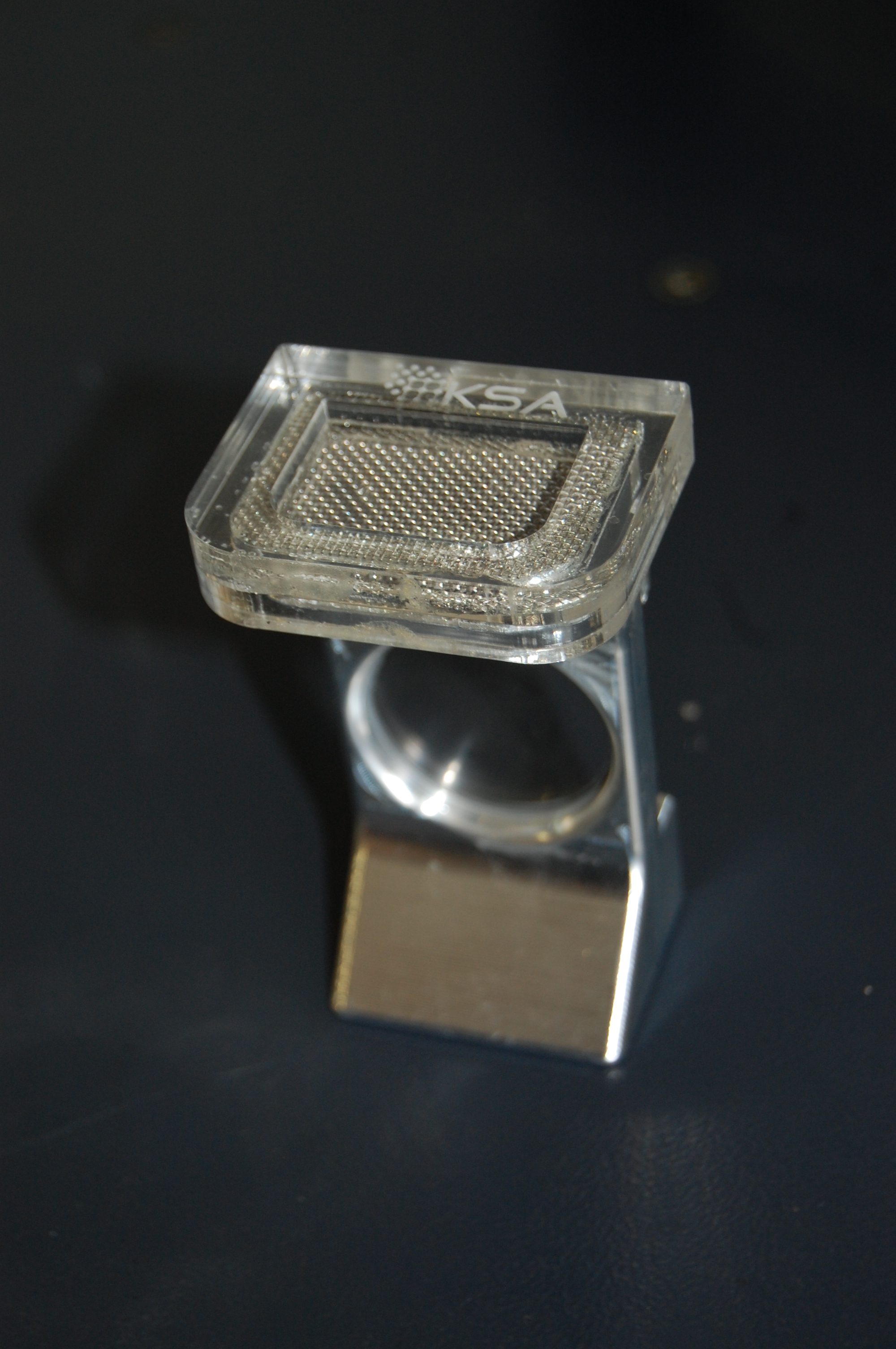
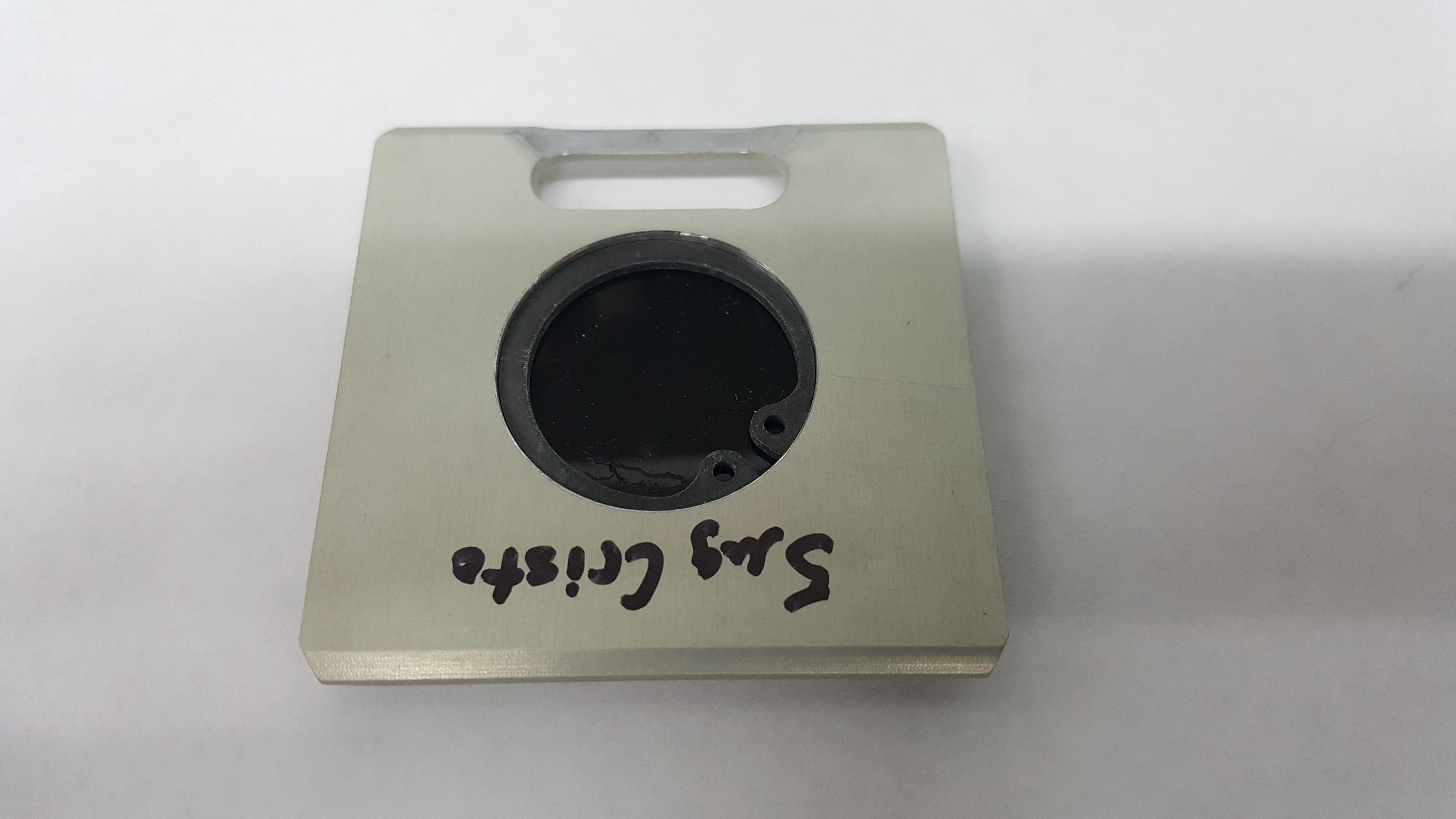
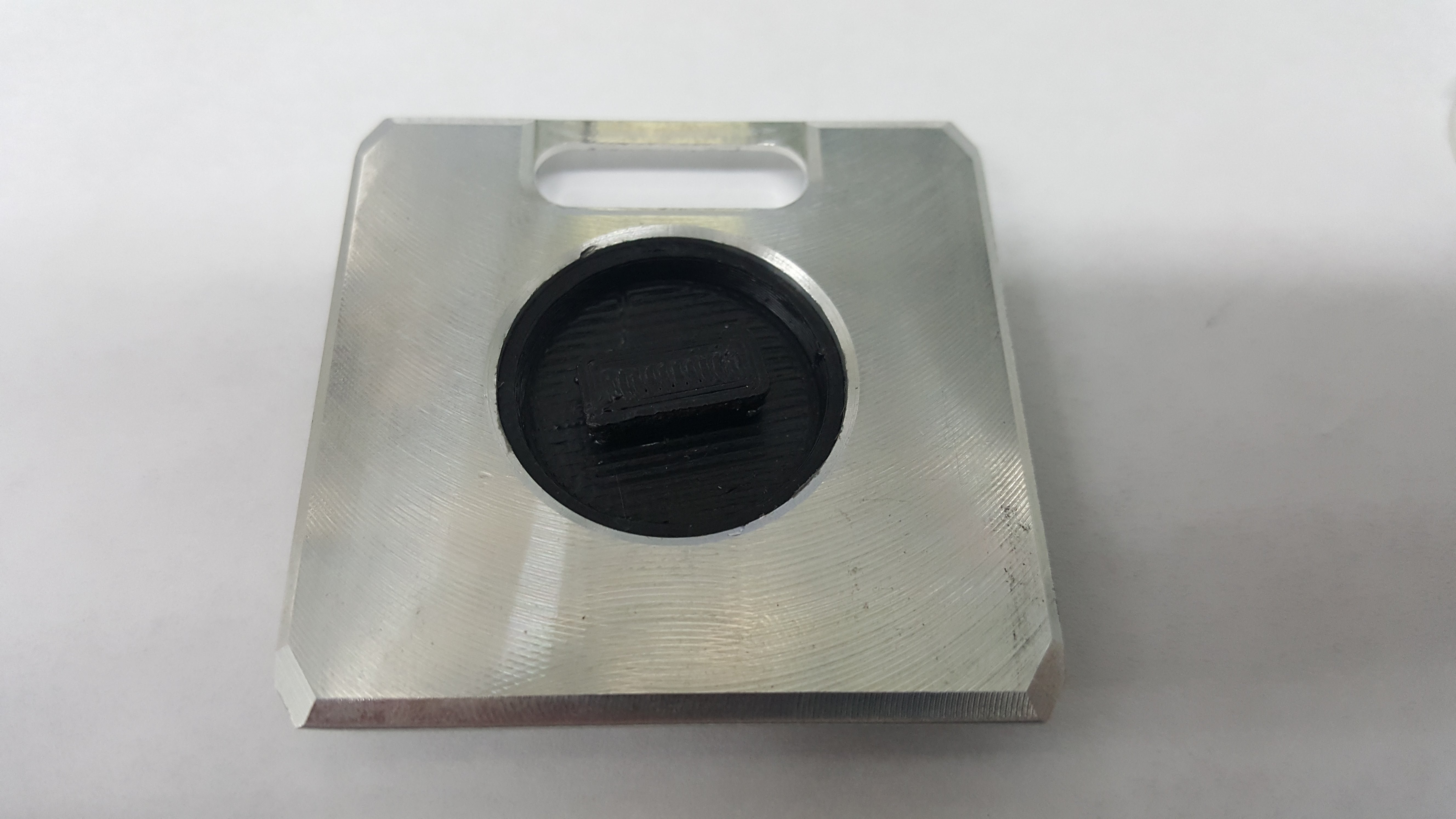
XRD patterns are complicated by a variety of undesirable effects. Some of which are easy to deal with, others are unavoidable. One of the issues we see often is scattering and diffraction effects that are actually being caused by the sample holder itself. These effects can usually be modeled out, but simply knowing which artifacts are being generated from scatter off the sample holder vs amorphous content or phases present in the sample itself can make the difference between an easy analysis and a grinding, iterative march toward a final result. One of the most common effect we see is scatter from plastic sample holders. Most of the sample holders we produce are either Aluminum or PMMA plastic, but either way, one of the easiest ways to avoid undesirable scatter is to simply enlarge the sample well. We’ve been doing this for decades on the standard, non-rotating sample holders by cutting a large, rectangular well rather than the standard, 25mm circular well.

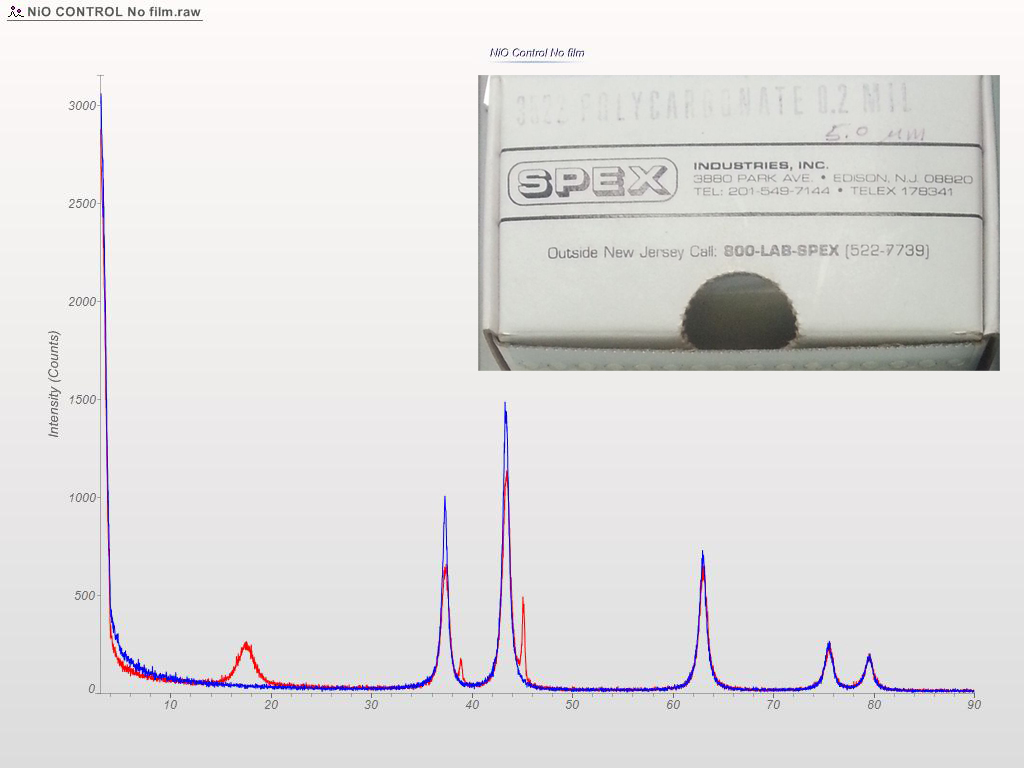
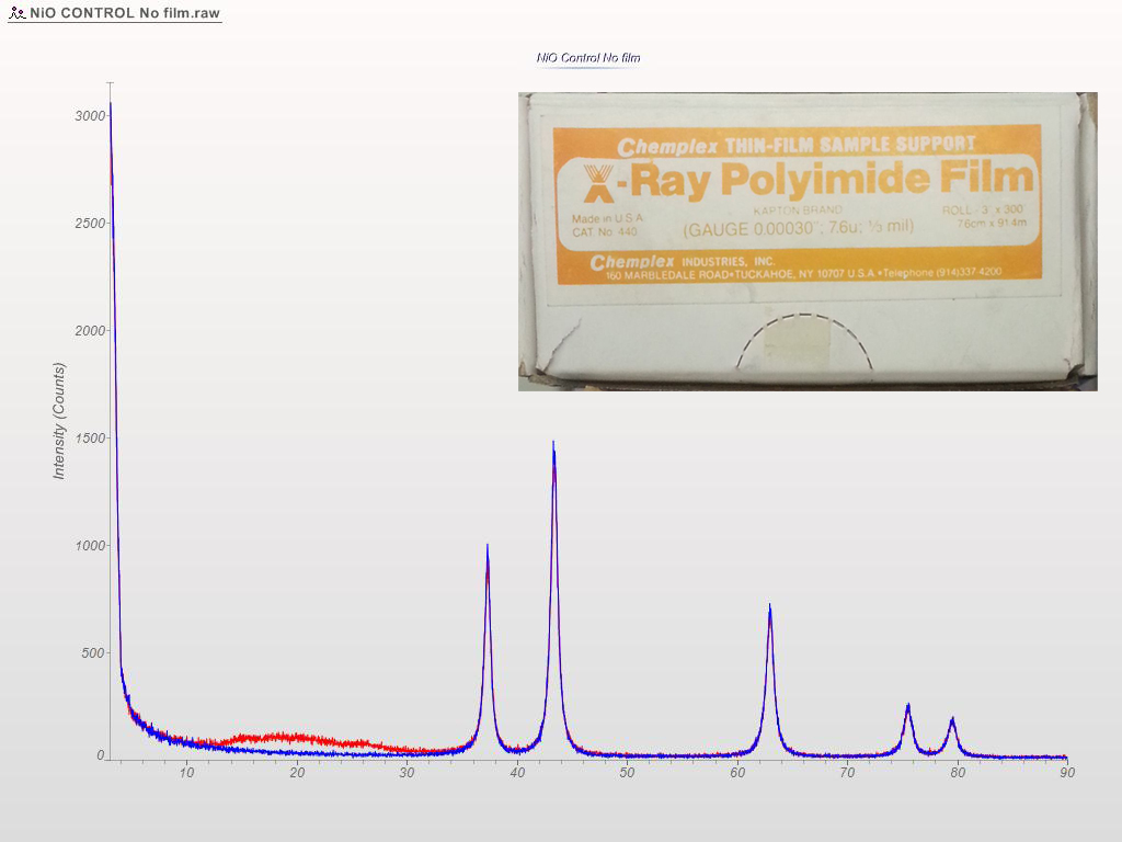
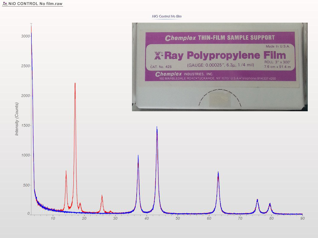
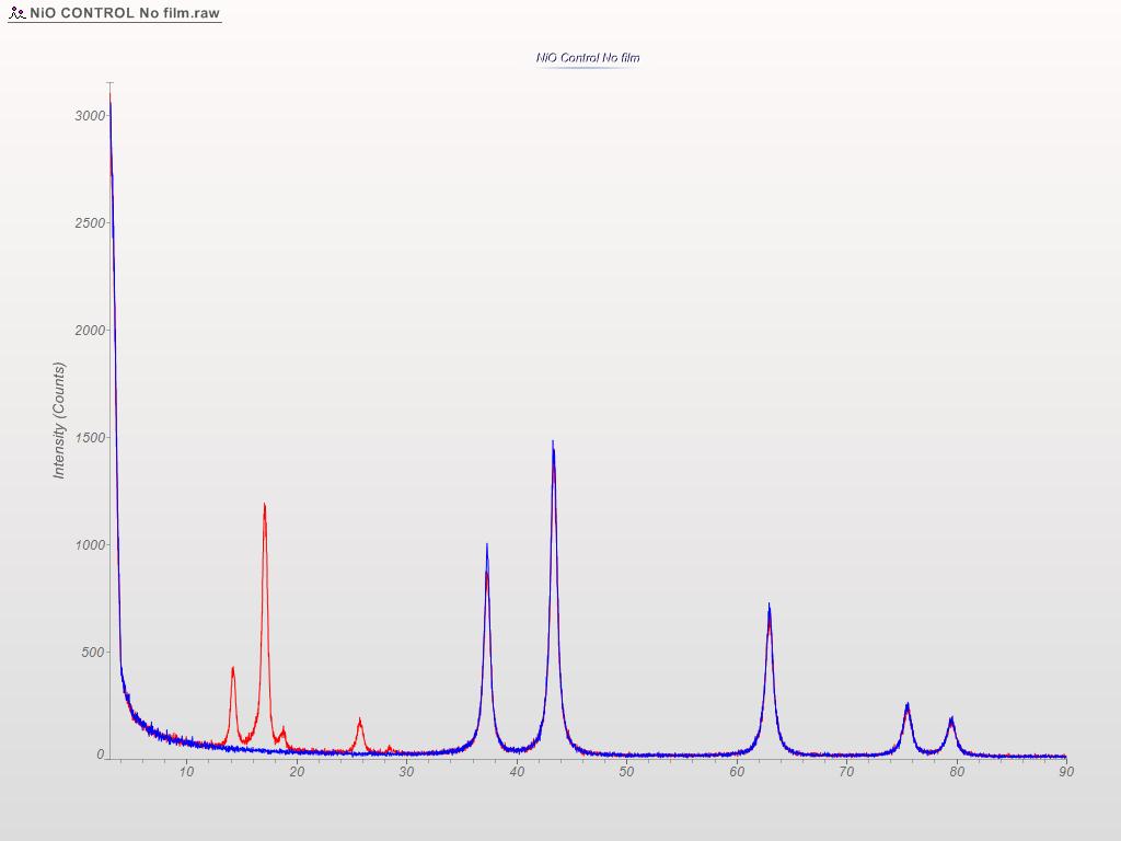
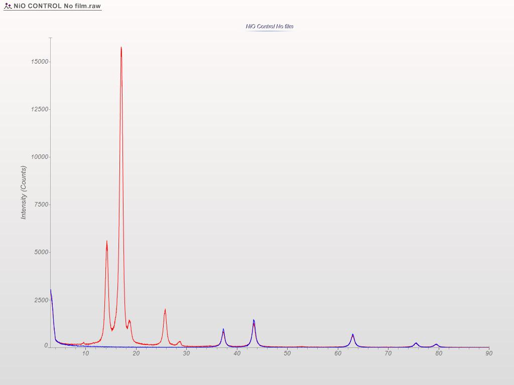
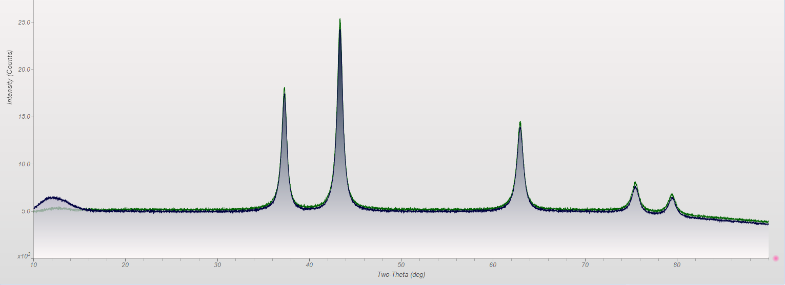
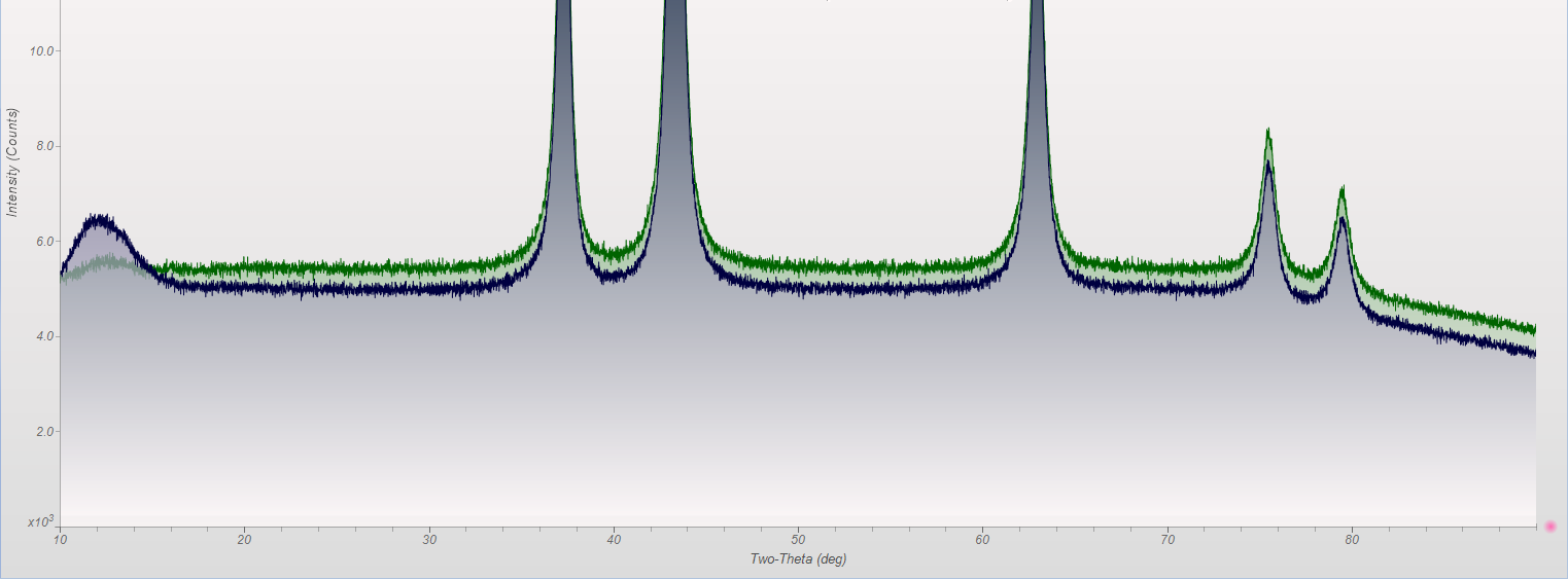
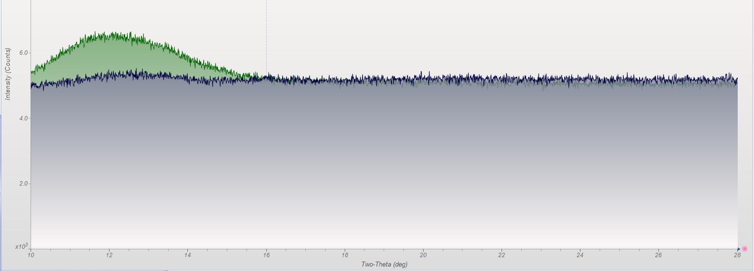
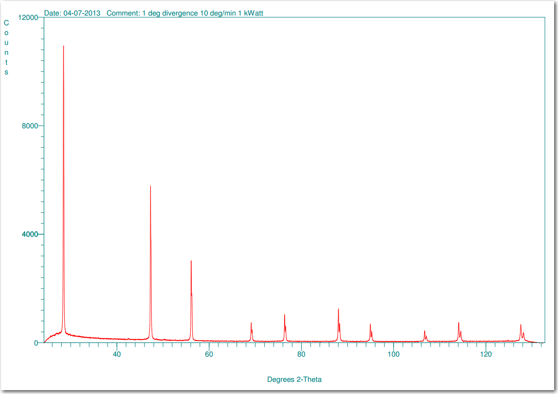
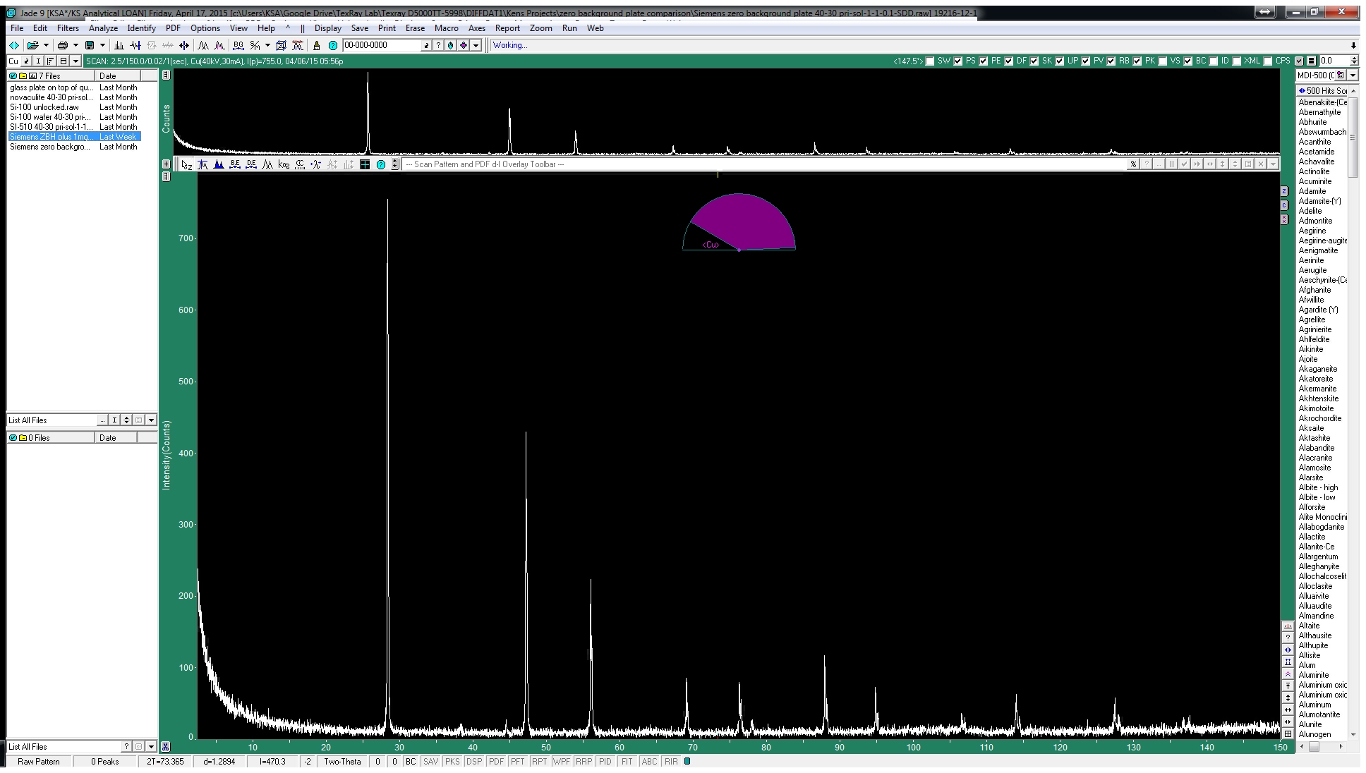
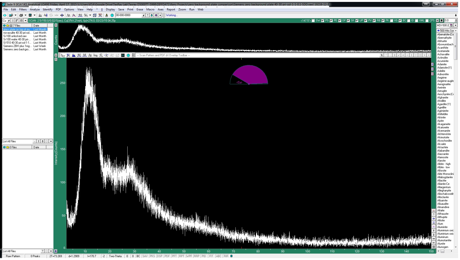
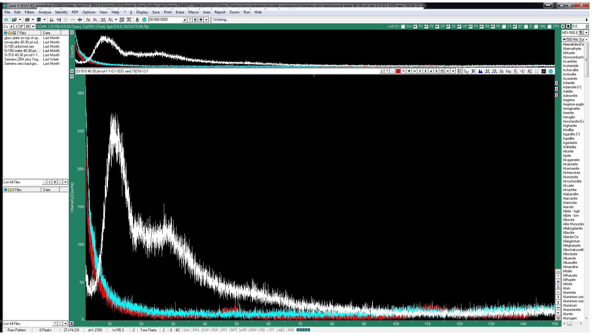
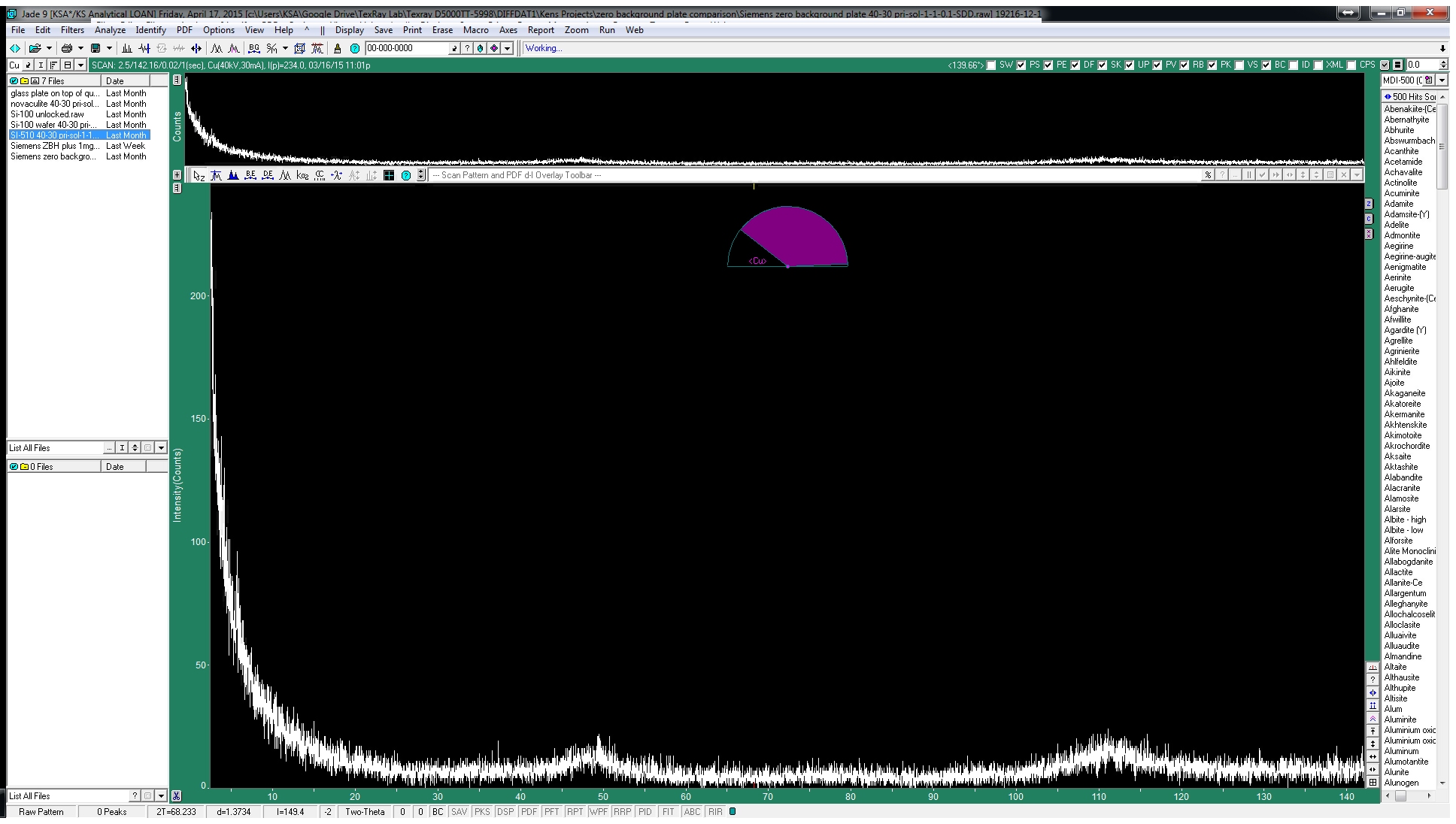
This week we did a little experiment to see just how much larger our sample well needed to be to eliminate the common PMMA hump at ~13 degrees 2Theta (Cu energy). It turns out that an increase of only 5mm in diameter made a huge difference in the total scatter even with very “wide-open” optics. See the scan images below for a real-world picture of the difference we saw. This may not seem like a significant problem until you’re looking for phases with D-spacings down in that region near the hump. Analysis of clay minerals can become particularly complicated. This is a great example of why we love talking to clients and XRD users around the world.


XRD sample prep is like a box of chocolates. You never know what you’re going to get… So many materials are fluffy or sticky that even after fine grinding, it’s common to have some clumps that just don’t want to break up. This became a problem for one of our clients using our side-loading tool so they added a piece of mesh to the mouth of the funnel. Their next order included a request for some type of removable solution for this so we mounted some coarse mesh in an acrylic frame that sits nicely on top of the funnel and makes it very easy to sift through sample material as it’s being loaded. We love these so they’ll be an option on all future orders!


You can never have enough sample holders no matter what machine you’re running. We’ve certainly found this to be true at Texray so we always try to keep a large number of them on-hand. KS Analytical Systems has always made one-off and custom sample holders for the Bruker instruments, but we’re now offering the standard PMMA powder holders as well at significant cost savings over the OEM version. The standard holder (25mm x 1mm deep well) is priced at $55 with bulk discounts starting at 20 holders.

Custom well depths, diameters, grooved floors, side-loading and zero-background versions are available.

Our PMMA holders are compatible with Bruker D8 Focus – D8 Advance (single, FlipStick autosampler, 90-position autosampler), D4 Endeavor and D2 Phaser (single only) systems. D500 and D5000 instruments can also use these holders.

We’ve brought the complete manufacturing process in-house to give us the freedom to make the custom designs our customer have always asked for. This includes custom laser etching. Company logos are a common request, but we’ve also started serializing sample holders on request. At Texray, we even etch them with barcodes for tracking samples through the data collection process.

The pictures below show a custom funnel tool for filling side-loading sample holders. The tool is machined from billet aluminum with an acrylic window on the funnel to make it easier to gauge fill level. The funnel itself is polished and the viewing plate which allows the users to see when the sample well is full is made of sapphire crystal for maximum scratch resistance.

It’s relatively common for us to receive very small volumes of material for analysis. Often this is the total amount available so getting the right answers is extremely important. When these come in as powders, the answer is always to run them on a zero background plate, but sometimes that’s not the case. Luckily, there are other options for analysis of very small quantities.

The most common application for filter-membrane sample holders has always been respirable silica quantification. This is mandated by OSHA and is an extremely common industrial hygiene test. Ambient air is sampled with a fixed or mobile suction system and particles are deposited onto a PVC membrane inside a sealed cartridge. Testing procedures are defined by NIOSH7500 and since this is a total quantification method (not a relative method), it’s critical that the entire sample is measured. Unfortunately, the measurement cannot be completed on the PVC membrane as received. Transferring the sample powder to an Ag membrane is accomplished by dissolving or ashing the PVC away, diluting the remainder in a solvent and depositing it onto the Ag membrane by vacuum filtration. The end result is an extremely low loss of analyte even for very small volumes of material.

This preparation method is also very useful for other types of samples which might have crystalline particulate suspended in a solution. Drying samples can be time-consuming, heating them to boil off liquid can cause phase transitions in the crystalline analyte, and handling dry powder in very small quantities is a very good way to lose material. Vacuum filtration solves all these problems.


Our most popular custom sample holder is the SC40F25 which is designed to hold the common 25mm Ag membrane filters used for this type of mounting. The anodized Al body is a time-tested design that works very well and causes almost no interference with the data, unlike the original injection-molded plastic parts. However, the most common method for retaining the membrane has always been to drop a metal support disk behind it and use an ID snap ring to retain both the disk and membrane. This can be a frustrating operation even for experienced hands. Snap rings are hard to control and the high spring tension gouges the inner diameter of the Aluminum body to the point that the holders must be replaced periodically.

After watching so many clients struggling with this system, we thought we could find a better option. The first step was a simple, laser cut acrylic backer instead of the metal disk. The acrylic was thicker which limited the depth to which the snap ring needed to be set. This was an improvement but still required the snap ring.

The next step was 3D printed plugs which could be pushed into the well. These supported the membrane and held it in the plane of diffraction at the same time. A standard pair of pliers was all the was needed to grab the plug and gently rotated it to release the membrane. This seemed like the ideal solution, but we heard from one user who claimed that the plug was causing an interfering peak in his measurements. We’ve been around the block with 3D printed sample holders in general and it’s definitely true that the common thermoplastics used will crystallize when cooled rapidly. This causes lots of problems for routine analysis of powders, but this was the first we’d heard of a peak being visible through an Ag membrane. Perhaps this user had a particularly thin membrane, but regardless, we needed a new solution, both for their lab and our own.


Our current solution is a laser cut “spring” backer which again combines the function of retainer and support in one part. The spring is easy to install by hand and can even be removed by hand, but forceps or needle-nose pliers make this easier. These have been working very well so we’re hopeful that this is going to be a long-term solution that we can share with our clients.


I spend a great deal of time meeting with XRD and XRF users throughout the year, but usually in the context of some problem or time-sensitive project. Luckily I’ve been able to attend the Denver X-ray Conference fairly consistently over the last few years. It’s a great time to catch up with other users who are as deeply invested in X-ray spectroscopy and crystallographic analysis as we are. The vendors always put on a great show in the exhibit hall and poster sessions.

The first three days of the week are filled with technical workshops focused on an array of topics. There are always some introductory classes for both XRD and XRF for new users to attend and then there will be additional topics which are usually more advanced. The educational opportunities alone are well worth the attendance fee. Each session is run by an expert in the field and questions, even from industrial users, are welcomed. The sessions are strictly non-sales oriented as well which lends the event a very egalitarian feeling. See the full program here.

Plenary sessions and more sales-oriented meetings occur later in the week and are a great way to get a feel for the cutting edge technology being released by the various vendors. The exhibit hall opens a few days into the conference so everyone has a few days to see all the different booths. We always spend a great deal of time at the Materials Data, Inc and Bruker-AXS booths in particular.

The conference moves between Westminster, CO just North of Denver, Chicago, IL and Big Sky, MT. I’ve never made the trek up to Big Sky, but I hear it’s beautiful. Some attendees only come when it’s up there.

I’d love to connect with as many of our readers as possible so contact us if you’ll be there and I’ll be sure to see you while I’m at DXC-Big Sky!

A great many factors affect the quality of data one can collect on any given instrument, but there are times when simply holding the aliquot is a major hurdle. We spend a great deal of time working out the best ways to hold odd samples and even create custom hardware to do so in some cases. Click here for some of our other posts related to the various sample holders we work with. Choosing the best sample holder for a given project is one thing, but there are also times when a completely different stage is required.

The most common stage is the simple, single sample stage. This relies on three pins to define the plane of diffraction. The sample holder is pressed against these pins by a spring loaded plunger beneath it.

FCT 0027 Xray decal visual croppedWe’ve been working with XRD machines for about 40 years now and to be quite honest, very little has changed. Most of the really exciting advancements have been software based, but there have certainly been changes to the hardware as well. We’ve introduced a few ourselves such as the KSA-SDD-150 detector. Automatic anti-scatter and divergence slits, additional axes and degrees of control have all increase the versatility of these instruments and opened them up to more advanced and unique experiments, but nothing has had an effect matching the new crop of Position Sensitive Detector (PSD). These have been around for decades, but didn’t really become popular until the a solid state version was introduced. There are still some trade-offs as mentioned in our KSA-SDD-150 post, but when you need speed, a PSD is the way to go.

Until recently, the only option for clients looking for this kind of speed was either a new XRD or a refurbished Bruker D8 system with a LynxEye or Vantec-1. While the D8 is a great machine and the LynxEye is a world class detector, the cost is usually too much for academic or small labs to bear. This has all been changing recently with the introduction of a truly aftermarket detector system from FCT ACTech. No other company that we’re aware of has worked so hard to make their hardware as turnkey as possible so the user isn’t left holding a box of parts and an instruction manual.

We can now offer detector upgrades for D5000 Theta/Theta and D5000 T2T systems with kits soon to be available for D500 systems as well. Software integration with DiffracPlus (standard software for Bruker XRD systems) is seamless and full integration with MDI Datascan is very close to completion. The future is very bright for users of these XRD systems.

Contact us for more information on these detectors


NovaculitesiliconKey features:

  • Data collection at 30x the speed of a standard point detector.
  • Dramatic increase in throughput
  • Plug-and-play retrofit
  • Maintenance free (no gas charge required)
  • Stand-alone operation for custom experiments
  • Excellent angular resolution


Technical Specifications:

  • Maximum count rate: 500Kcps / pixcel, 50Mcps global
  • Maximum scanning speed: 120 deg/min
  • Angular resolution: 0.06 deg at 200mm radius
  • Strip pitch: 120um
  • Number of channels: 96
  • Angular span: 3.3 degrees
  • Energy resolution: <10%
  • Energy range: 4.5KeV to 17KeV, efficiency at 30KeV is 10%
  • Compatible with all common XRD tube anodes including Cr, Fe, Co, Cu, Mo and W.

The majority of the samples we receive come in volumes high enough to completely fill the well in any of our standard sample holders. Some are too large or oddly shaped which calls for a special holding solution like those listed here, but many are simply very small quantities of powder. Placing these in a standard holder would leave them well outside the plane of diffraction and provide terrible data, not to mention substantial scatter
or diffracted background from whatever the powder is placed on. The answer is a zero background sample holder (ZBH). Most our users at KS Analytical Systems run the original Siemens/Bruker plates, but others are using Si(100) and even glass substrates. We’re very happy to say that
we’re able to offer a direct replacement for these with our new ZBH-32 holders. These fit most Siemens XRD systems and can be customized for use in most any other system. Contact us for more information on this. The scan below shows the data collected from a single mg of Silicon 640B standard powder spread across a ZBH.

Off Planar Quartz ZBH w-1mg 640B

Full scan of 1mg Silicon 640B standard spread across a ZBH

ZBH-32

ZBH-32 sample holders mounted for Siemens and Bruker single sample stages.


Some users report acceptable results using simple glass plates. While there are serious caveats here, it may be a reasonable solution for some users. The issue with amorphous glass is not diffracted peaks in the background, but rather, scatter off the surface. X-ray scattering off a surface is inversely proportional to the average atomic number of that material. That is to say, the lighter the matrix, the more efficiently it will scatter X-rays. This is why we use a pure Graphite sample to characterize the emission spectra of our XRF instrumentation. The glass sample shows the expected scatter “hump” starting at a very low angle and it doesn’t flatten until nearly 100°2Θ. While some of this can be modeled and subtracted with good profile fitting software like Jade 2010, it can be challenging to match the data quality of a good ZBH. We’re working on a series of videos to guide new users through some of these features, but on-site training classes are also available.


Glass plate

Amorphous glass empty

Glass-Qtz-Si510 overlay

Glass, ZBH-32 and off-planar quartz scans overlayed for comparison


Several of our customers in the geological industry use standard Si(100) wafers. These can be a great solution, but again have serious drawbacks for some applications. The Si(100) material creates diffracted peaks which are very sharp and therefore easier to model out sometimes, but also very high as the material is monocrystalline. The scan below shows what happens when one tries to run a normal scan across a bare plate. The largest peaks are actually only one or two which have over loaded the detector and caused it to drop out. All of these scans were collected with our SDD-150 which can handle up to 1×10^6 cps, but for the sake of good comparison, we left it tuned as it would be for a standard pattern. The monocrystalline nature of this material causes big problems, but it also allows for a creative solution. See the second scan for the results of the same measurement with the plate angled 1 degree off of theoretical. With this geometry, it’s unlikely this would affect the data quality dramatically, but the offending peaks are drastically diminished.


Si-100 wafer

Si-100 empty

Si-100 locked vs unlocked

Si-100 standard vs skewed scan


Off-planar Quartz holders have been the industry standard for decades. Historically, these have been made from solid, monocrystalline quartz material cut at a specific angle (6° off the C axis if I’m not mistaken). While these work well, they can be inconsistent. Even some of the OEM holders we’ve tested have shown some peaks which we can’t explain. Talking to some very experienced crystallographers, we find that they’ve had similar experiences.


Off Planar Quartz ZBH

Off-planar Quartz empty

ZBH-32 empty

ZBH-32 empty


We’ve been looking for a better answer for several years, but there are few off-the-shelf materials which work as well as off-planar quartz. The ideal answer was to cut solid Si(100) oriented billets such that the face presented to the diffractometer had no d-spacings which would diffract in the normal range of these machines. This is not unlike the off-planar Quartz method, but the starting material is much more consistent and durable. Si(510) offers very low background as well as the consistency of a manufactured product. The new ZBH-32 sample holders from KSA come in two versions, ZBH-25 and ZBH-32 with the latter being ideally suited for rotating stages and low angle work.


20141124_161938Our recent sealed sample cell project required a thin covering film to be applied over loose powder before analysis by XRD. We tested a few options for this film as part of the design process and the results were interesting enough that we thought it would be worth dedicating a full post to that data and expanding the range of materials a bit to satisfy our curiosity.

All data was collected on our primary powder system. This is a Siemens D5000 configured with a theta/theta goniometer, automatic anti-scatter and divergence slits, a standard sealed Cu tube (LFF) and our new KSA-XRD-150 detector system. We alternate between a digital phi stage, 40-position autosampler and the standard, single sample stage which was used in these experiments. I had a spare sealed-sample cell available which made it easy to exchange the films without disturbing the sample surface. The design of these stretches the film taught each time the cell is assembled. I’d originally tried to simply lay the film over a side-load holder, but without being tightly held, it would buckle enough that results at low angles were probably affected. A NiO standard powder was used due to its high purity and compositional difference from any of the film materials.

The data clearly shows that Polyimide was the best choice for this application as it resulted in very limited attenuation as well as an extremely minimal increase in background intensity/amorphous scatter. Some of the other patterns were very interesting though.

20141124_161656 NiO CONTROL No film


NiO Prolene copy NiO Mylar copy


NiO Polycarbonate copy NiO Polyimide copy


NiO Polypropylene copy


NiO Prolene

Scotch “Magic” office tape. Adhesive side down.

NiO Scotch packing

Scotch “Heavy duty” packing tape. Adhesive side down.


Over the past 15 years, Barnett Shale has become a major resource for natural gas in Texas.  Being located in the North Texas region, it is easy to see the boom of drilling rigs and wells popping up in the suburban and rural areas between Ft. Worth and Denton.  Collaborations between Geologists at universities and major oil companies have put a large amount of research into characterizing shale.  In 2001, Środoń et al. published a journal article in Clays and Clay Minerals that discussed the importance of sample preparation for sediments, such as shale, to be analyzed using X-ray diffraction.

Powder X-ray diffraction is the preferred and best technique to identify and quantify mineral compositions in geological materials such as rocks, sediments, and soils.  Sample preparation and loading are two important factors for accurate quantitative XRD analysis using Rietveld refinement.  Proper sample grinding and using a side-loader or backside loader are common practices to avoid preferred orientation.  At Texray, we have a variety of sample holders for different applications, and we can even custom build holders for those random parts.  However, in this study we wanted to see for ourselves the effect of sample grinding and particle size, and also we wanted to test out our new McCrone Micronizing Mill.  We already knew what the results would be from experience and previous work by Środoń et al., 2001 and Klug and Alexander, 1974, but this was a fun experiment to try with shale.

Shale rock from the North Texas region

Shale Rock from the North Texas region

The rocks (pictured above) were broken up into smaller pieces using a mortar and pestle, and then half was transferred to the McCrone mill for wet grinding and the other half we continued to grind manually using the mortar and pestle.  By the way if you are running out of bench space in the laboratory and are looking for a mill, I highly recommend the McCrone Micronizing Mill because it takes up very the little space and it’s capable of grinding below 10 μm in less than 10 minutes.  After grinding, we loaded the powder samples into a backside loader and analyzed them using a Bruker D5000 X-ray Diffractometer.

Shale XRD Pattern

XRD pattern of Mortar & Pestle Ground Shale (blue) vs McCrone Mill Ground Shale (red)

In the XRD pattern shown above the main differences you will notice between the two grinding methods are peak intensities and a small 2-theta peak shift.  Both of these differences are effects related to particle size distribution and sample loading.  Wet grinding the shale in a McCrone Mill creates smaller uniform particles (~5μm), therefore when loading the sample into holders the powders pack easier and tighter creating a denser layer of material for the X-rays to penetrate, hence higher peak intensities compared to manual grinding.  Sample preparation is one of the most important aspects to quantitative XRD because of preferred orientation and sample displacement.  In order to reduce user error such as, induced preferred orientation, it is essential we learn from previous research and take the proper steps to prepare samples.  The ICDD is a great source for free literature on applications involving XRD and XRF.  We will be posting more discussions on sample preparation and applications in the future.