AN ANALYTICAL XRAY SERVICES LABORATORY
Feel free to call us: 940-784-3002

I spend a great deal of time meeting with XRD and XRF users throughout the year, but usually in the context of some problem or time-sensitive project. Luckily I’ve been able to attend the Denver X-ray Conference fairly consistently over the last few years. It’s a great time to catch up with other users who are as deeply invested in X-ray spectroscopy and crystallographic analysis as we are. The vendors always put on a great show in the exhibit hall and poster sessions.

The first three days of the week are filled with technical workshops focused on an array of topics. There are always some introductory classes for both XRD and XRF for new users to attend and then there will be additional topics which are usually more advanced. The educational opportunities alone are well worth the attendance fee. Each session is run by an expert in the field and questions, even from industrial users, are welcomed. The sessions are strictly non-sales oriented as well which lends the event a very egalitarian feeling. See the full program here.

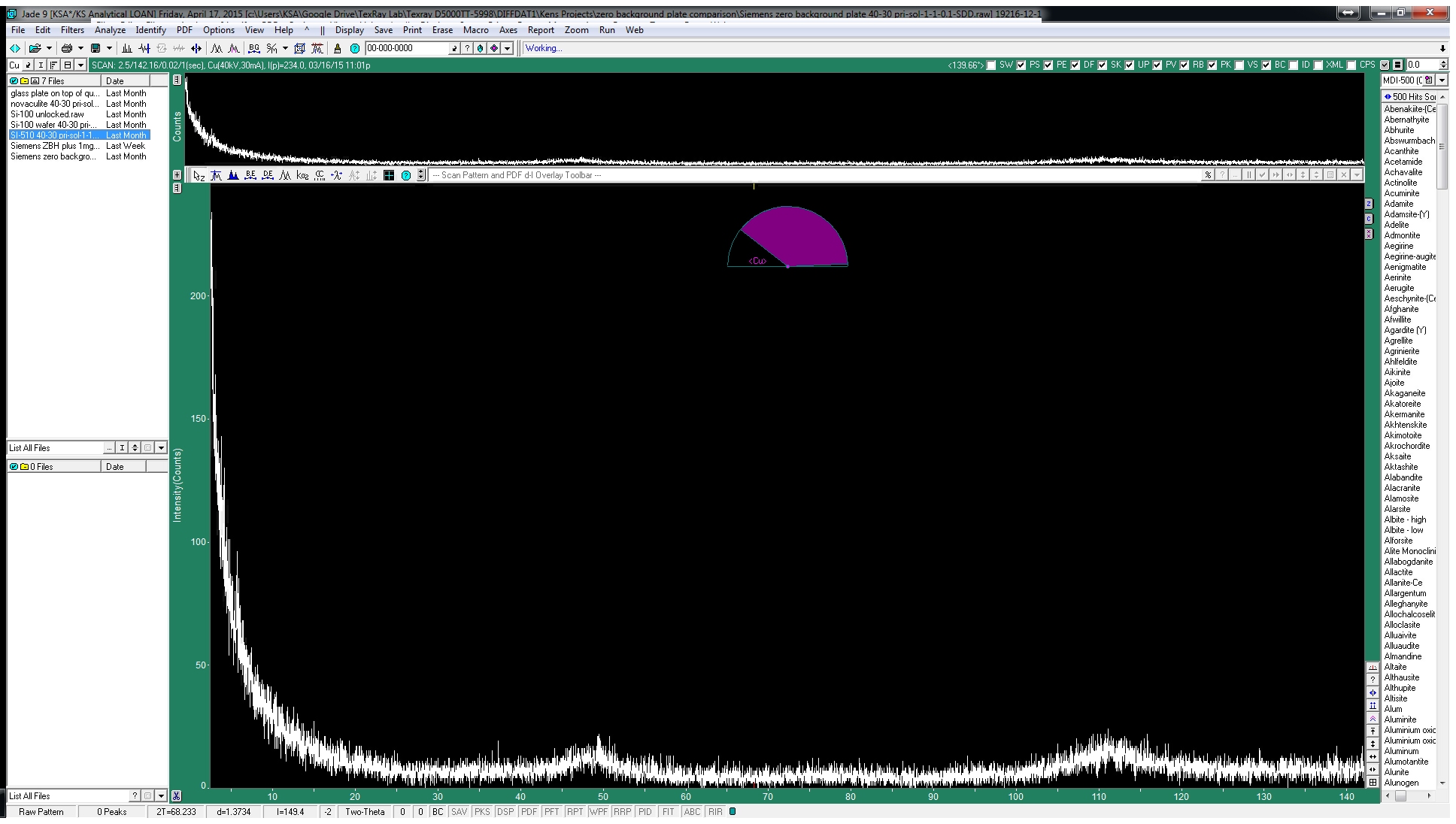
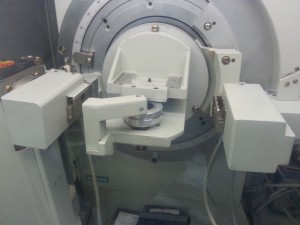
Plenary sessions and more sales-oriented meetings occur later in the week and are a great way to get a feel for the cutting edge technology being released by the various vendors. The exhibit hall opens a few days into the conference so everyone has a few days to see all the different booths. We always spend a great deal of time at the Materials Data, Inc and Bruker-AXS booths in particular.

The conference moves between Westminster, CO just North of Denver, Chicago, IL and Big Sky, MT. I’ve never made the trek up to Big Sky, but I hear it’s beautiful. Some attendees only come when it’s up there.

I’d love to connect with as many of our readers as possible so contact us if you’ll be there and I’ll be sure to see you while I’m at DXC-Big Sky!

A great many factors affect the quality of data one can collect on any given instrument, but there are times when simply holding the aliquot is a major hurdle. We spend a great deal of time working out the best ways to hold odd samples and even create custom hardware to do so in some cases. Click here for some of our other posts related to the various sample holders we work with. Choosing the best sample holder for a given project is one thing, but there are also times when a completely different stage is required.

The most common stage is the simple, single sample stage. This relies on three pins to define the plane of diffraction. The sample holder is pressed against these pins by a spring loaded plunger beneath it.

The dreaded “amorphous” hump created by x-rays scattering off plastic sample holders has plagued XRD users for decades. It’s a serious enough problem that we make a good volume of these holders from Aluminum which works very well for loose powders. The plastic scatters xrays at around 13 degrees 2Theta (Cu anode tube) which make a real mess of most geological patterns and isn’t fun to model out for Rietveld refinement. Zero background holders like our ZBH-32 work wonderfully in standard sample stages designed for a single sample at a time, but the large plate isn’t compatible with the autosampler.


I recently had a request for a hybrid holder which would allow for analysis of very small volumes of materials while retaining compatibility with the autosampler. This is almost identical to our standard powder holders, but with a well designed specifically for our small ZBH plate.

Key features include:

  • 6061-T6 Al material (anodized or as-machined)
  • Si(510) plate
  • Raised sample well minimizes the area of the sample holder in the plane of diffraction. (Original Siemens design)
  • Beveled well walls minimize the area of Al in the plane of diffraction
  • Other small modifications are made to improve reliability of these holders in the autosampler

One of the fundamental facts of lab-based X-ray production is that our x-ray tubes emit much more than the pure KA1 lines we rely on for material characterization and quantification. Most XRD users are familiar with techniques and hardware for the reduction or elimination of KB1, W LA1 and Bremsstrahlung, but take for granted the inseparable pair of KA1 and KA2 (referred to as the “doublet”). Luckily for us, these energies are present in strict proportion such that we can factor their paired presence into most XRD analysis to the point that one might barely notice their effect. However, the fact remains that we will see peak broadening at lower angles and completely independent additional peaks at higher angles due to this superfluous discrete emission.

Separating the doublet cannot be accomplished electronically or through absorption/attenuation such as might be effective for KB1 energies. It must be done in the primary-beam with an additional diffraction event. Primary-beam monochromators are generally classified by the number of diffraction events required for a photon to pass completely through the device. Single-bounce, 2-bounce and 4-bounce geometries are common with the latter providing the best energy resolution allbeit the lowest intensity (photon flux). My limited experience suggests that while the single-bounce models retain enough intensity to have some application in powder XRD, the others are relegated to HR-XRD applications such as XRR.

The alignment for any of this hardware is not for the faint of heart as it begins with coarse adjustments using fluorescent screens in the beam path. This was essential for us given how dramatically misaligned the monochromator had become after so many attempts to bring it back into operation. We actually needed our SDD system to verify that we were tuning for Cu KA1 energy rather than the KB1 emissions because some of the most basic aspects of the alignment had pushed way beyond their intended position.

Along the way we built ourselves a motorized remote adjustment tool which we’ll return to the user as small adjustments are required on a regular basis with this kind of monochromator to retain maximum intensity. It’s quite useful and even versatile enough to allow for the adjustment of multiple control knobs.

One final note regarding intensity. It’s easy to get excited about energy resolution like this, but bear in mind that we’re looking at ~20x reduction in intensity due to the inherent losses involved in the primary diffraction event. This data was collected at 10x the normal speed and at half the normal 2Theta step increment so it looks very good, but one would need a compelling reason to slow their data collection this much.

Another side effect of performing your energy discrimination in the primary beampath is that other issues such as fluorescence effects (incident x-rays exciting elements in the sample causing high background intensities) are harder to avoid than they would be with a diffracted-beam monochromator. The 4x reduction in intensity inherent in the diffracted-beam monochromatization makes it a poor choice to eliminate these effects when the incident intensities are already so low. We recommend energy-dispersive detectors such as our SDD-150 to eliminate extraneous energies without sacrificing net intensity. We’ve also worked with the Bruker LynxEye XE-T detector which has a very high energy resolution compared to other position sensitive detectors (PSD). Contact KS Analytical Systems for more information on these options.

FCT 0027 Xray decal visual croppedWe’ve been working with XRD machines for about 40 years now and to be quite honest, very little has changed. Most of the really exciting advancements have been software based, but there have certainly been changes to the hardware as well. We’ve introduced a few ourselves such as the KSA-SDD-150 detector. Automatic anti-scatter and divergence slits, additional axes and degrees of control have all increase the versatility of these instruments and opened them up to more advanced and unique experiments, but nothing has had an effect matching the new crop of Position Sensitive Detector (PSD). These have been around for decades, but didn’t really become popular until the a solid state version was introduced. There are still some trade-offs as mentioned in our KSA-SDD-150 post, but when you need speed, a PSD is the way to go.

Until recently, the only option for clients looking for this kind of speed was either a new XRD or a refurbished Bruker D8 system with a LynxEye or Vantec-1. While the D8 is a great machine and the LynxEye is a world class detector, the cost is usually too much for academic or small labs to bear. This has all been changing recently with the introduction of a truly aftermarket detector system from FCT ACTech. No other company that we’re aware of has worked so hard to make their hardware as turnkey as possible so the user isn’t left holding a box of parts and an instruction manual.

We can now offer detector upgrades for D5000 Theta/Theta and D5000 T2T systems with kits soon to be available for D500 systems as well. Software integration with DiffracPlus (standard software for Bruker XRD systems) is seamless and full integration with MDI Datascan is very close to completion. The future is very bright for users of these XRD systems.

Contact us for more information on these detectors


NovaculitesiliconKey features:

  • Data collection at 30x the speed of a standard point detector.
  • Dramatic increase in throughput
  • Plug-and-play retrofit
  • Maintenance free (no gas charge required)
  • Stand-alone operation for custom experiments
  • Excellent angular resolution


Technical Specifications:

  • Maximum count rate: 500Kcps / pixcel, 50Mcps global
  • Maximum scanning speed: 120 deg/min
  • Angular resolution: 0.06 deg at 200mm radius
  • Strip pitch: 120um
  • Number of channels: 96
  • Angular span: 3.3 degrees
  • Energy resolution: <10%
  • Energy range: 4.5KeV to 17KeV, efficiency at 30KeV is 10%
  • Compatible with all common XRD tube anodes including Cr, Fe, Co, Cu, Mo and W.

XRD sample holders are easily the most common items we’re asked to machine. Sometimes it’s because they’re no longer available, but usually, it’s to accommodate some special application. Sometimes it’s as simple as making them from Aluminum to allow for cleaning with acetone or other harsh solvents. Other times it has more to do with the clients preferred style of loading or sample volume. The end result is that there’s very little consistency so our process needs to be as versatile as possible. This video highlights the most recent process. It’s hard to see exactly what’s going on through the coolant, but this is a test run of a program to cut special holders for 25mm filter membrane holders for respirable silica measurements (or anything else one might want to deposit onto a 25mm filter). It’s cutting the bottom of one holder and the top of another (each on its own side of the fixture).  A full load of these produces 6 complete holders for every run.

Siemens goniometers are about as sturdy as they come. Large diameter gears and bearings spread out forces across a wide area resulting in smooth and stable performance as well as very high load handling due to the added leverage of this arrangement. For this reason, they’ll run for many years even after the grease inside has become hard and contaminated with dust. Most users don’t even know their goniometer is getting stiff until we check it during a PM. Catching this before the goniometer starts to hang up saves thousands of dollars and weeks of down time. Our goniometer rebuild service involves complete disassembly of the goniometer down to individual ball bearings for a thorough cleaning. We’ve tried to duplicate this procedure on-site with very limited success as the large components are best cleaned in a full size solvent bath and it’s special brackets are required to avoid concentricity issues during reassembly. All the critical electronics are replaced during reassembly along with fresh lubrication. The best case scenario is that we catch issue far enough in advance to get a matching replacement goniometer rebuilt and shipped out. There are too many variants to keep rebuilt units in stock all the time. This way we only need to come to the site once to swap the goniometer and perform the necessary zero alignment. The old goniometer goes back in the same crate and we’re done in a day or two. Waiting till a hard failure of the goniometer means a trip out to identify the problem and disassemble the system. The goniometer is shipped in for a rebuild which can easily take a few days to complete before being shipped back along with a second on-site visit. I’d estimate the extra cost to be right around $6k plus the cost of shipping and two weeks of downtime. We certainly don’t mind going this route, but if it were my money, I’d rather spend it on a comprehensive check of the machine rather than emergency services.

These pictures are from one of our first full rebuilds. This instrument was installed in a D5000-MATIC instrument at a cement plant. I’ve never seen so much dust inside a goniometer. Another particularly rough one was from a horizontal goniometer on a single-crystal system at a university. The students had a terrible habit of breaking Si(100) wafers and dropping them onto the goniometer face. Those little shards made their way into the bearings resulting in a rather perilous rebuild with shards of Si throughout it.

Posted by: In: Uncategorized 07 Sep 2015 0 comments Tags: , , , ,

Every once in a while we get a call for components destined for custom equipment. NIST has built some extremely precise XRD instrumentation from various base components. These are operated in highly controlled environments to qualify certified reference materials (CRM). Some of our other clients have built much more proprietary, but no less impressive systems which I’d love to show in detail if the designs weren’t closely guarded intellectual property.

One of the most interesting and exciting projects we’ve seen recently is the hard-xray monochromator system developed by Dr. Gerald Seidler of University of Washington and his colleagues. The instrument itself has myriad applications, but the general idea is that many experiments which currently require synchrotron time can be performed in a laboratory setting. We’ve worked on other projects like this which were meant more qualification systems to avoid wasting synchrotron time if the experiment didn’t actually require it, but Dr. Seidlers instrument is geared toward bringing XAFS, XES and XANES right into the lab setting.  Read the full paper here.Capture

The majority of the samples we receive come in volumes high enough to completely fill the well in any of our standard sample holders. Some are too large or oddly shaped which calls for a special holding solution like those listed here, but many are simply very small quantities of powder. Placing these in a standard holder would leave them well outside the plane of diffraction and provide terrible data, not to mention substantial scatter
or diffracted background from whatever the powder is placed on. The answer is a zero background sample holder (ZBH). Most our users at KS Analytical Systems run the original Siemens/Bruker plates, but others are using Si(100) and even glass substrates. We’re very happy to say that
we’re able to offer a direct replacement for these with our new ZBH-32 holders. These fit most Siemens XRD systems and can be customized for use in most any other system. Contact us for more information on this. The scan below shows the data collected from a single mg of Silicon 640B standard powder spread across a ZBH.

Off Planar Quartz ZBH w-1mg 640B

Full scan of 1mg Silicon 640B standard spread across a ZBH

ZBH-32

ZBH-32 sample holders mounted for Siemens and Bruker single sample stages.


Some users report acceptable results using simple glass plates. While there are serious caveats here, it may be a reasonable solution for some users. The issue with amorphous glass is not diffracted peaks in the background, but rather, scatter off the surface. X-ray scattering off a surface is inversely proportional to the average atomic number of that material. That is to say, the lighter the matrix, the more efficiently it will scatter X-rays. This is why we use a pure Graphite sample to characterize the emission spectra of our XRF instrumentation. The glass sample shows the expected scatter “hump” starting at a very low angle and it doesn’t flatten until nearly 100°2Θ. While some of this can be modeled and subtracted with good profile fitting software like Jade 2010, it can be challenging to match the data quality of a good ZBH. We’re working on a series of videos to guide new users through some of these features, but on-site training classes are also available.


Glass plate

Amorphous glass empty

Glass-Qtz-Si510 overlay

Glass, ZBH-32 and off-planar quartz scans overlayed for comparison


Several of our customers in the geological industry use standard Si(100) wafers. These can be a great solution, but again have serious drawbacks for some applications. The Si(100) material creates diffracted peaks which are very sharp and therefore easier to model out sometimes, but also very high as the material is monocrystalline. The scan below shows what happens when one tries to run a normal scan across a bare plate. The largest peaks are actually only one or two which have over loaded the detector and caused it to drop out. All of these scans were collected with our SDD-150 which can handle up to 1×10^6 cps, but for the sake of good comparison, we left it tuned as it would be for a standard pattern. The monocrystalline nature of this material causes big problems, but it also allows for a creative solution. See the second scan for the results of the same measurement with the plate angled 1 degree off of theoretical. With this geometry, it’s unlikely this would affect the data quality dramatically, but the offending peaks are drastically diminished.


Si-100 wafer

Si-100 empty

Si-100 locked vs unlocked

Si-100 standard vs skewed scan


Off-planar Quartz holders have been the industry standard for decades. Historically, these have been made from solid, monocrystalline quartz material cut at a specific angle (6° off the C axis if I’m not mistaken). While these work well, they can be inconsistent. Even some of the OEM holders we’ve tested have shown some peaks which we can’t explain. Talking to some very experienced crystallographers, we find that they’ve had similar experiences.


Off Planar Quartz ZBH

Off-planar Quartz empty

ZBH-32 empty

ZBH-32 empty


We’ve been looking for a better answer for several years, but there are few off-the-shelf materials which work as well as off-planar quartz. The ideal answer was to cut solid Si(100) oriented billets such that the face presented to the diffractometer had no d-spacings which would diffract in the normal range of these machines. This is not unlike the off-planar Quartz method, but the starting material is much more consistent and durable. Si(510) offers very low background as well as the consistency of a manufactured product. The new ZBH-32 sample holders from KSA come in two versions, ZBH-25 and ZBH-32 with the latter being ideally suited for rotating stages and low angle work.


20141124_161938Our recent sealed sample cell project required a thin covering film to be applied over loose powder before analysis by XRD. We tested a few options for this film as part of the design process and the results were interesting enough that we thought it would be worth dedicating a full post to that data and expanding the range of materials a bit to satisfy our curiosity.

All data was collected on our primary powder system. This is a Siemens D5000 configured with a theta/theta goniometer, automatic anti-scatter and divergence slits, a standard sealed Cu tube (LFF) and our new KSA-XRD-150 detector system. We alternate between a digital phi stage, 40-position autosampler and the standard, single sample stage which was used in these experiments. I had a spare sealed-sample cell available which made it easy to exchange the films without disturbing the sample surface. The design of these stretches the film taught each time the cell is assembled. I’d originally tried to simply lay the film over a side-load holder, but without being tightly held, it would buckle enough that results at low angles were probably affected. A NiO standard powder was used due to its high purity and compositional difference from any of the film materials.

The data clearly shows that Polyimide was the best choice for this application as it resulted in very limited attenuation as well as an extremely minimal increase in background intensity/amorphous scatter. Some of the other patterns were very interesting though.

20141124_161656 NiO CONTROL No film


NiO Prolene copy NiO Mylar copy


NiO Polycarbonate copy NiO Polyimide copy


NiO Polypropylene copy


NiO Prolene

Scotch “Magic” office tape. Adhesive side down.

NiO Scotch packing

Scotch “Heavy duty” packing tape. Adhesive side down.